- 您现在的位置:买卖IC网 > Sheet目录39249 > LM4050AI8.2MDC (NATIONAL SEMICONDUCTOR CORP) 1-OUTPUT TWO TERM VOLTAGE REFERENCE, 8.192 V, UUC
Absolute Maximum Ratings (Note 1)
If Military/Aerospace specified devices are required,
please contact the National Semiconductor Sales Office/
Distributors for availability and specifications.
Reverse Current
20 mA
Forward Current
10 mA
Power Dissipation (T
A = 25C) (Note 2)
M3 Package
280 mW
Storage Temperature
65C to +150C
Lead Temperature
M3 Package
Vapor phase (60 seconds)
+215C
Infrared (15 seconds)
+220C
ESD Susceptibility
Human Body Model (Note 3)
2 kV
Machine Model (Note 3)
200V
See AN-450 “Surface Mounting Methods and Their Effect
on Product Reliability” for other methods of soldering
surface mount devices.
Operating Ratings (Note 2)
Temperature Range
(T
min
≤ T
A
≤ T
max)
Industrial Temperature
Range
40C
≤ T
A
≤ +85C
Extended temperature
Range
40C
≤ T
A
≤ +125C
Reverse Current
LM4050-2.5
60 A to 15 mA
LM4050-4.1
68 A to 15 mA
LM4050-5.0
74 A to 15 mA
LM4050-8.2
91 A to 15 mA
LM4050-10.0
100 A to 15 mA
LM4050-2.5
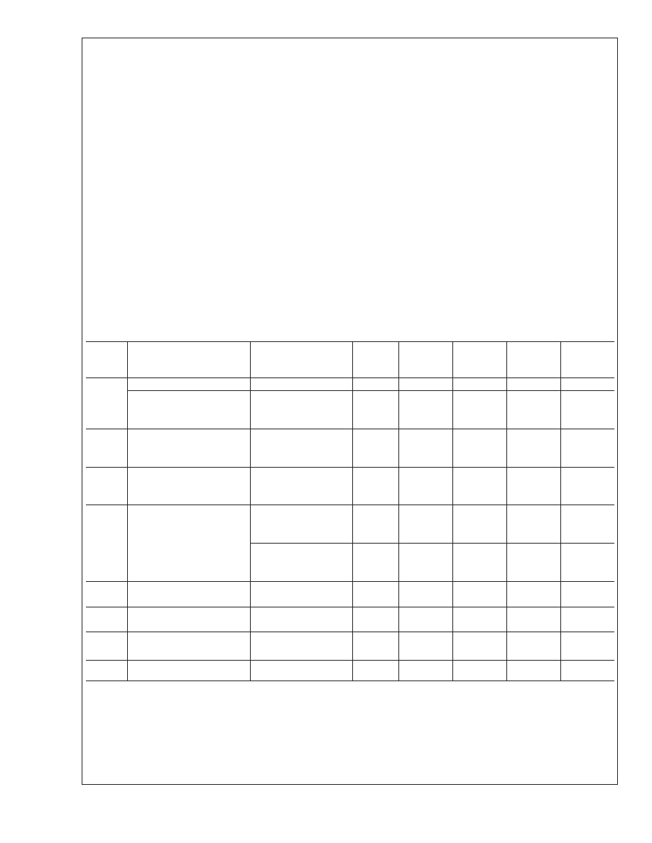
Electrical Characteristics
Boldface limits apply for T
A =TJ =TMIN to TMAX; all other limits TA =TJ = 25C. The grades A, B and C designate initial
Reverse Breakdown Voltage tolerances of ±0.1%, ±0.2%, and 0.5% respectively.
Symbol
Parameter
Conditions
Typical
LM4050AIM3
LM4050AEM3
Limits
LM4050BIM3
LM4050BEM3
Limits
LM4050CIM3
LM4050CEM3
Limits
Units
(Limit)
VR
Reverse Breakdown Voltage
IR = 100 A
2.500
V
Reverse Breakdown Voltage
Tolerance (Note 6)
IR = 100 A
±2.5
±5.0
±13
mV (max)
Industrial Temp. Range
±11
±14
±21
mV (max)
Extended Temp. Range
±15
±18
±25
mV (max)
IRMIN
Minimum Operating Current
41
A
60
A (max)
65
A (max)
VR/T
Average Reverse Breakdown
Voltage Temperature Coefficient
IR =10 mA
±20
ppm/C
IR =1 mA
±15
ppm/C
IR = 100 A
±15
±50
ppm/C (max)
VR/IR
Reverse Breakdown Voltage
Change with Operating Current
Change (Note 7)
IRMIN ≤ IR ≤ 1 mA
0.3
mV
0.8
mV (max)
1.2
mV (max)
1mA
≤ IR ≤ 15 mA
2.3
mV
6.0
mV (max)
8.0
mV (max)
ZR
Reverse Dynamic Impedance
IR = 1 mA, f = 120 Hz, IAC
= 0.1 IR
0.3
eN
Wideband Noise
IR = 100 A
41
Vrms
10 Hz
≤ f ≤ 10 kHz
VR
Reverse Breakdown Voltage
Long Term Stability
t = 1000 hrs
T = 25C ±0.1C
IR = 100 A
120
ppm
VHYST
Thermal Hysteresis
T = 40C to 125C
0.7
mV
LM4050
www.national.com
4
发布紧急采购,3分钟左右您将得到回复。
相关PDF资料
LM4050AI-10MDC
1-OUTPUT TWO TERM VOLTAGE REFERENCE, 10 V, UUC
LM4050AI-5MDC
1-OUTPUT TWO TERM VOLTAGE REFERENCE, 5 V, UUC
LM4050BI-5MDA
1-OUTPUT TWO TERM VOLTAGE REFERENCE, 5 V, UUC
LM4050BIM3-2.5+T
1-OUTPUT TWO TERM VOLTAGE REFERENCE, 2.5 V, PDSO3
LM4050AIM3-4.1+T
1-OUTPUT TWO TERM VOLTAGE REFERENCE, 4.096 V, PDSO3
LM4051BIM3-1.2+T
1-OUTPUT TWO TERM VOLTAGE REFERENCE, 1.225 V, PDSO3
LM4050BIX3-5.0+T
1-OUTPUT TWO TERM VOLTAGE REFERENCE, 5 V, PDSO3
LM4050BIM3-2.1+T
1-OUTPUT TWO TERM VOLTAGE REFERENCE, 2.048 V, PDSO3
相关代理商/技术参数
LM4050AIM3-10
功能描述:基准电压& 基准电流 RoHS:否 制造商:STMicroelectronics 产品:Voltage References 拓扑结构:Shunt References 参考类型:Programmable 输出电压:1.24 V to 18 V 初始准确度:0.25 % 平均温度系数(典型值):100 PPM / C 串联 VREF - 输入电压(最大值): 串联 VREF - 输入电压(最小值): 分流电流(最大值):60 mA 最大工作温度:+ 125 C 封装 / 箱体:SOT-23-3L 封装:Reel
LM4050AIM3-10/NOPB
功能描述:基准电压& 基准电流 RoHS:否 制造商:STMicroelectronics 产品:Voltage References 拓扑结构:Shunt References 参考类型:Programmable 输出电压:1.24 V to 18 V 初始准确度:0.25 % 平均温度系数(典型值):100 PPM / C 串联 VREF - 输入电压(最大值): 串联 VREF - 输入电压(最小值): 分流电流(最大值):60 mA 最大工作温度:+ 125 C 封装 / 箱体:SOT-23-3L 封装:Reel
LM4050AIM3-10/NOPB
制造商:Texas Instruments 功能描述:, Voltage Reference Type:Shunt, Referenc
LM4050AIM3-2.0/NOPB
功能描述:IC VREF SHUNT PREC 2.048V SOT23 RoHS:是 类别:集成电路 (IC) >> PMIC - 电压基准 系列:- 标准包装:3,000 系列:- 基准类型:旁路,精度 输出电压:5V 容差:±0.5% 温度系数:100ppm/°C 输入电压:- 通道数:1 电流 - 阴极:80µA 电流 - 静态:- 电流 - 输出:15mA 工作温度:-40°C ~ 85°C 安装类型:表面贴装 封装/外壳:TO-236-3,SC-59,SOT-23-3 供应商设备封装:SOT-23-3 包装:带卷 (TR) 其它名称:LM4040CIM3-5.0MLTRLM4040CIM3-5.0MLTR-ND
LM4050AIM3-2.1
制造商:Maxim Integrated Products 功能描述:50PPM/+C PRECISION MICROPOWER SHUNT - Rail/Tube
LM4050AIM3-2.1+
制造商:Rochester Electronics LLC 功能描述: 制造商:Maxim Integrated Products 功能描述:
LM4050AIM3-2.1+T
制造商:Rochester Electronics LLC 功能描述: 制造商:Maxim Integrated Products 功能描述:
LM4050AIM3-2.1-T
功能描述:基准电压& 基准电流 RoHS:否 制造商:STMicroelectronics 产品:Voltage References 拓扑结构:Shunt References 参考类型:Programmable 输出电压:1.24 V to 18 V 初始准确度:0.25 % 平均温度系数(典型值):100 PPM / C 串联 VREF - 输入电压(最大值): 串联 VREF - 输入电压(最小值): 分流电流(最大值):60 mA 最大工作温度:+ 125 C 封装 / 箱体:SOT-23-3L 封装:Reel
